- 您现在的位置:买卖IC网 > Sheet目录307 > ADE7758ARWZRL (Analog Devices Inc)IC ENERGY METERING 3PHASE 24SOIC
�� �
�
�Data� Sheet�
�Phase� A,� Phase� B,� and� Phase� C� zero� crossings� are,� respectively,�
�included� when� counting� the� number� of� half-line� cycles� by�
�setting� ZXSEL[0:2]� bits� (Bit� 3� to� Bit� 5)� in� the� LCYCMODE�
�ADE7758�
�v� =� rms� voltage.�
�i� =� rms� current.�
�θ� =� total� phase� shift� caused� by� the� reactive� elements� in� the� load.�
�Then� the� instantaneous� reactive� power� q(t)� can� be� expressed� as�
�q� (� t� )� =� VI� cos� ?� ?� –� θ� –�
�?� –� VI� cos� ?� 2� ωt� –� θ� –�
�π� ?� ?� π� ?�
�?�
�2� ?�
�?�
�2� ?�
�register.� Any� combination� of� the� zero� crossings� from� all� three�
�phases� can� be� used� for� counting� the� zero� crossing.� Only� one�
�phase� should� be� selected� at� a� time� for� inclusion� in� the� zero�
�crossings� count� during� calibration� (see� the� Calibration� section).�
�The� number� of� zero� crossings� is� specified� by� the� LINECYC�
�register.� LINECYC� is� an� unsigned� 16-bit� register.� The� ADE7758�
�can� accumulate� active� power� for� up� to� 65535� combined� zero�
�crossings.� Note� that� the� internal� zero-crossing� counter� is� always�
�active.� By� setting� the� LWATT� bit,� the� first� energy� accumulation�
�result� is,� therefore,� incorrect.� Writing� to� the� LINECYC� register�
�q� (� t� )� =� v� (� t� )� ×� i� ′� (� t� )�
�?�
�where� i� ′� (� t� )� is� the� current� waveform� phase� shifted� by� 90°.�
�Note� that� q� (� t� )� can� be� rewritten� as�
�q� (� t� )� =� VI� sin� (� θ� )� +� VI� sin� (� 2� ωt� –� θ� )�
�The� average� reactive� power� over� an� integral� number� of� line�
�cycles� (n)� is� given� by� the� expression� in� Equation� 31.�
�(29)�
�(30)�
�∫� q� (� t� )� dt� =� V� ×� I� ×� sin� (� θ� )�
�when� the� LWATT� bit� is� set� resets� the� zero-crossing� counter,� thus�
�ensuring� that� the� first� energy� accumulation� result� is� accurate.�
�Q� =�
�1� nT�
�nT� 0�
�(31)�
�At� the� end� of� an� energy� calibration� cycle,� the� LENERGY� bit�
�(Bit� 12)� in� the� STATUS� register� is� set.� If� the� corresponding�
�mask� bit� in� the� interrupt� mask� register� is� enabled,� the� IRQ�
�output� also� goes� active� low;� thus,� the� IRQ� can� also� be� used� to�
�signal� the� end� of� a� calibration.�
�Because� active� power� is� integrated� on� an� integer� number� of� half-�
�line� cycles� in� this� mode,� the� sinusoidal� component� is� reduced� to�
�0,� eliminating� any� ripple� in� the� energy� calculation.� Therefore,� total�
�energy� accumulated� using� the� line-cycle� accumulation� mode� is�
�where:�
�T� is� the� period� of� the� line� cycle.�
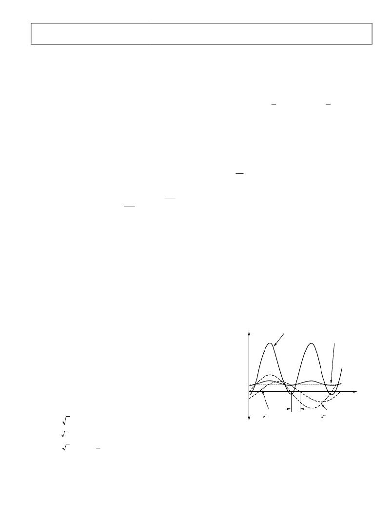
�Q� is� referred� to� as� the� average� reactive� power.� The� instantaneous�
�reactive� power� signal� q� (� t� )� is� generated� by� multiplying� the�
�voltage� signals� and� the� 90°� phase-shifted� current� in� each� phase.�
�The� dc� component� of� the� instantaneous� reactive� power� signal� in�
�each� phase� (A,� B,� and� C)� is� then� extracted� by� a� low-pass� filter� to�
�obtain� the� average� reactive� power� information� on� each� phase.�
�This� process� is� illustrated� in� Figure� 72.� The� reactive� power� of�
�E� (� t� )� =� VRMS� � IRMS� � t�
�(26)�
�each� phase� is� accumulated� in� the� corresponding� 16-bit� VAR-�
�where� t� is� the� accumulation� time.�
�Note� that� line� cycle� active� energy� accumulation� uses� the� same�
�signal� path� as� the� active� energy� accumulation.� The� LSB� size� of�
�these� two� methods� is� equivalent.� Using� the� line� cycle� accumula-�
�tion� to� calculate� the� kWh/LSB� constant� results� in� a� value� that�
�can� be� applied� to� the� WATTHR� registers� when� the� line�
�accumulation� mode� is� not� selected� (see� the� Calibration� section).�
�REACTIVE� POWER� CALCULATION�
�A� load� that� contains� a� reactive� element� (inductor� or� capacitor)�
�produces� a� phase� difference� between� the� applied� ac� voltage� and�
�the� resulting� current.� The� power� associated� with� reactive� elements�
�is� called� reactive� power,� and� its� unit� is� VAR.� Reactive� power� is�
�defined� as� the� product� of� the� voltage� and� current� waveforms� when�
�one� of� these� signals� is� phase� shifted� by� 90°.�
�Equation� 30� gives� an� expression� for� the� instantaneous� reactive�
�power� signal� in� an� ac� system� when� the� phase� of� the� current�
�hour� register� (AVARHR,� BVARHR,� or� CVARHR).� The� input� to�
�each� reactive� energy� register� can� be� changed� depending� on� the�
�accumulation� mode� setting� (see� Table� 21).�
�The� frequency� response� of� the� LPF� in� the� reactive� power� signal�
�path� is� identical� to� that� of� the� LPF2� used� in� the� average� active�
�power� calculation� (see� Figure� 66).�
�INSTANTANEOUS�
�REACTIVE� POWER� SIGNAL�
�q(t)� =� VRMS� ×� IRMS� ×� sin(� φ� )� +� VRMS� ×� IRMS� ×� sin(2� ω� t� +� θ� )�
�AVERAGE� REACTIVE� POWER� SIGNAL� =�
�VRMS� ×� IRMS� ×� sin(� θ� )�
�VRMS� ×� IRMS� ×� sin(� φ� )�
�0x00000�
�channel� is� shifted� by� +90°.�
�v� (� t� )� =� 2� V� sin� (� ωt� –� θ� )�
�i� (� t� )� =� 2� I� sin� (� ωt� )�
�(27)�
�θ�
�VOLTAGE� CURRENT�
�v(t)� =� 2� ×� VRMS� ×� sin(� ω� t� –� θ� )� i(t)� =� 2� ×� IRMS� ×� sin(� ω� t)�
�Figure� 72.� Reactive� Power� Calculation�
�The� low-pass� filter� is� nonideal,� so� the� reactive� power� signal� has�
�i� ′� (� t� )� =� 2� I� sin� ?� ?� ωt� +�
�π� ?�
�2� ?�
�where:�
�?�
�?�
�(28)�
�some� ripple.� This� ripple� is� sinusoidal� and� has� a� frequency� equal�
�to� 2� the� line� frequency.� Because� the� ripple� is� sinusoidal�
�in� nature,� it� is� removed� when� the� reactive� power� signal� is�
�integrated� over� time� to� calculate� the� reactive� energy.�
�Rev.� E� |� Page� 35� of� 72�
�发布紧急采购,3分钟左右您将得到回复。
相关PDF资料
ADE7761AARSZ-RL
IC ENERGY METERING 1PHASE 20SSOP
ADE7761BARSZ-RL
IC ENERGY METERING 1PHASE 20SSOP
ADE7768ARZ-RL
IC ENERGY METERING 1PHASE 16SOIC
ADE7769ARZ-RL
IC ENERGY METERING 1PHASE 16SOIC
ADM8843ACPZ-REEL7
IC LED DRVR WHITE BCKLGT 16LFCSP
ADP1653ACPZ-R7
IC LED DRVR PHOTO FLASH 16-LFCSP
ADP1712-EVALZ
BOARD EVALUATION ADP1712
ADP1720-EVALZ
BOARD EVAL FOR ADP1720-ADJ
相关代理商/技术参数
ADE7759
制造商:AD 制造商全称:Analog Devices 功能描述:Active Energy Metering IC with di/dt Sensor Interface
ADE7759ARS
功能描述:IC ENERGY METERING 1PHASE 20SSOP RoHS:否 类别:集成电路 (IC) >> PMIC - 能量测量 系列:- 产品培训模块:Lead (SnPb) Finish for COTS
Obsolescence Mitigation Program 标准包装:2,500 系列:*
ADE7759ARSRL
功能描述:IC ENERGY METERING 1PHASE 20SSOP RoHS:否 类别:集成电路 (IC) >> PMIC - 能量测量 系列:- 产品培训模块:Lead (SnPb) Finish for COTS
Obsolescence Mitigation Program 标准包装:2,500 系列:*
ADE7759ARSZ
功能描述:IC ENERGY METERING 1PHASE 20SSOP RoHS:是 类别:集成电路 (IC) >> PMIC - 能量测量 系列:- 产品培训模块:Lead (SnPb) Finish for COTS
Obsolescence Mitigation Program 标准包装:2,500 系列:*
ADE7759ARSZRL
功能描述:IC ENERGY METERING 1PHASE 20SSOP RoHS:是 类别:集成电路 (IC) >> PMIC - 能量测量 系列:- 产品培训模块:Lead (SnPb) Finish for COTS
Obsolescence Mitigation Program 标准包装:2,500 系列:*
ADE7760
制造商:AD 制造商全称:Analog Devices 功能描述:Energy Metering IC with On-Chip Fault Detection
ADE7760ARS
制造商:Analog Devices 功能描述:Energy Measurement 20-Pin SSOP 制造商:Analog Devices 功能描述:ENERGY METER IC W/ ONCHIP FAULT & OSCIL. - Rail/Tube
ADE7760ARSRL
制造商:Analog Devices 功能描述:Energy Measurement 20-Pin SSOP T/R 制造商:Analog Devices 功能描述:ENERGY METER IC W/ONCHIP FAULT & OSCIL. - Tape and Reel